


video
Profile
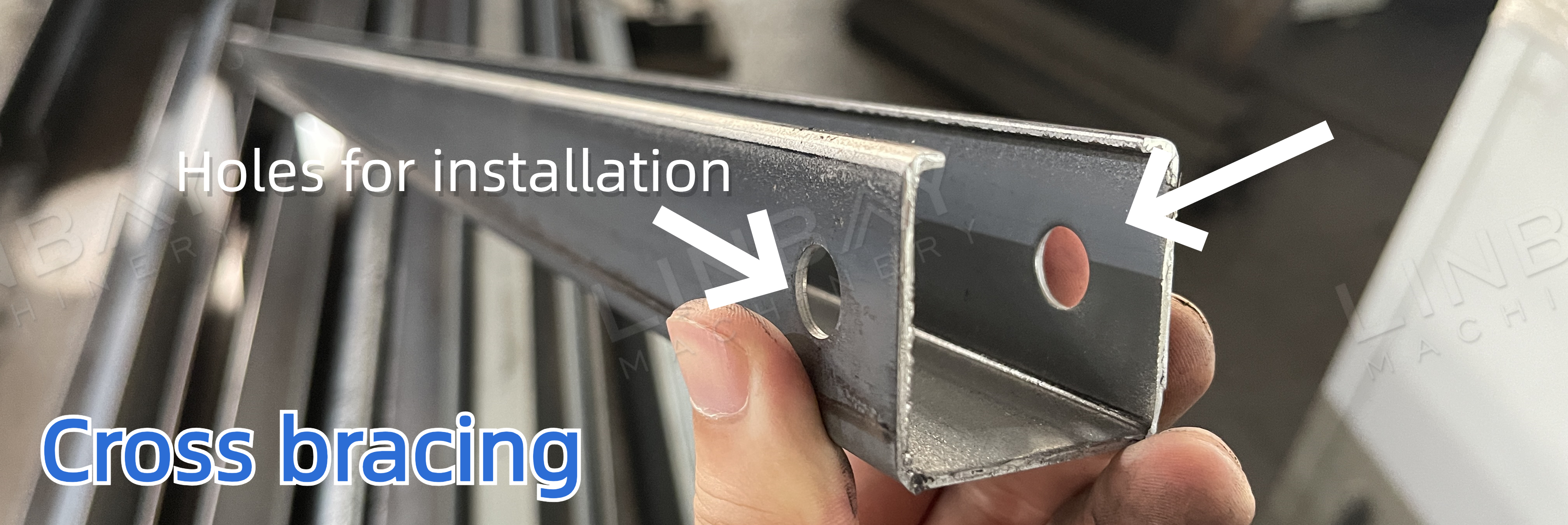
Cross bracing is crucial for heavy-duty rack systems, providing diagonal support between two uprights. It helps prevent wobbling and maintains structural alignment under heavy loads. Typically, cross bracing is made from hot-rolled, cold-rolled, or galvanized steel with a thickness of 1.5 to 2 mm.
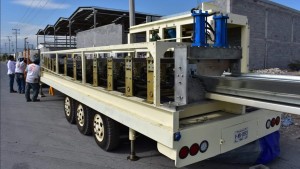
Traditionally, cross bracing has been produced using bending machines. However, the roll forming machine line, which includes uncoiling, leveling, roll forming, punching, and cutting, offers higher automation and reduced manual labor costs. This solution has become the preferred choice for many clients due to its efficiency and cost-effectiveness.
The punching styles vary depending on the installation method:
Installation Method 1: A single brace is installed inside the rack upright, requiring pre-punched holes at the bracing height for screw installation.
Installation Method 2: Two braces are installed inside the rack upright, requiring pre-punched holes at the bottom of the bracing for screw installation.
Real case-Main Techinical Parameters
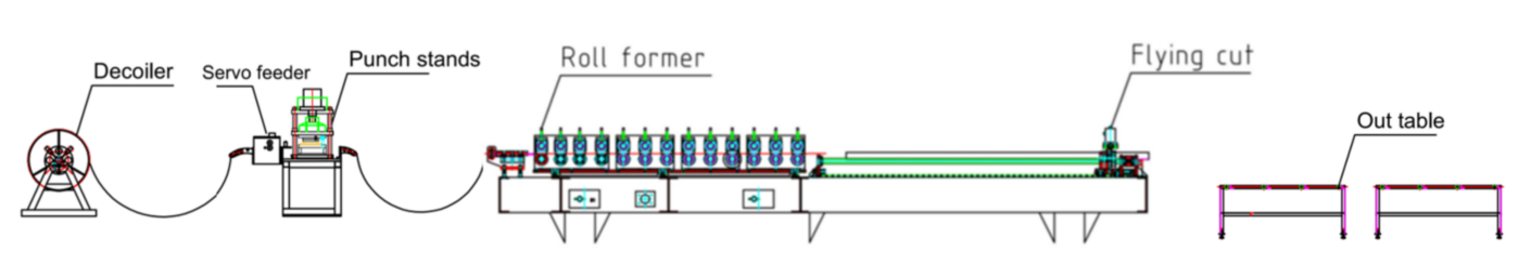
Flow chart: Decoiler--Servo feeder--Hydraulic punch--Guiding--Roll forming machine--Flying hydraulic cutting--Out table
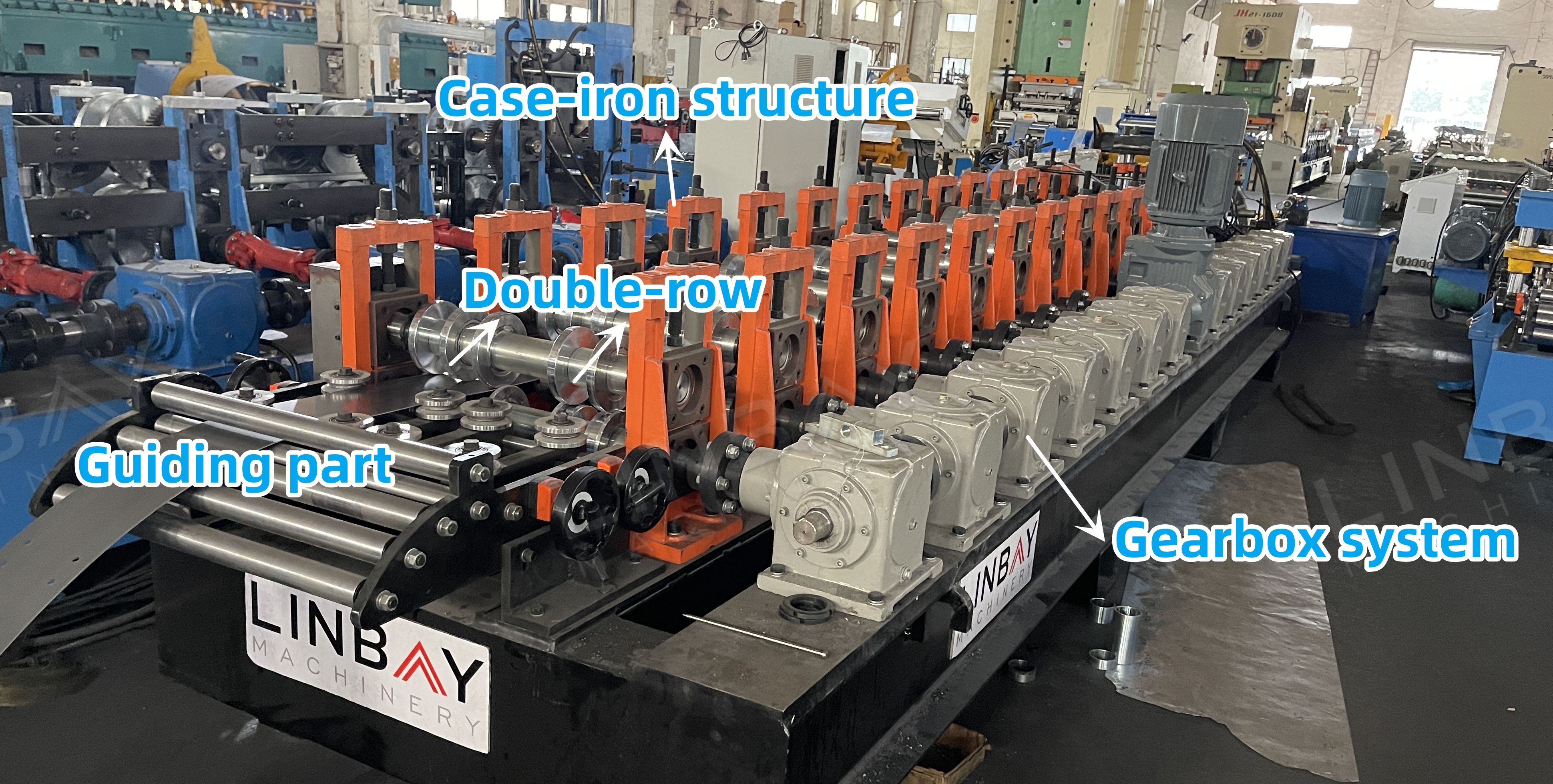
Compared to two single-row production lines, a dual-row production line can save you the cost of an additional forming machine, decoiler, and servo feeder, as well as the space required for another production line. Additionally, the dual-row structure reduces the time cost for changing sizes, unlike manual size changes on a single line, thereby enhancing efficiency.
Real case-Main Technical Parameters
1.Line speed:4-6m/min, adjustable
2.Suitable material:Hot rolled steel, cold rolled steel, galvanized steel
3.Material thickness: 1.5-2mm.
4.Roll forming machine: Cast-iron structure
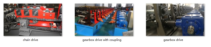
5.Driving system: Gearbox driving system
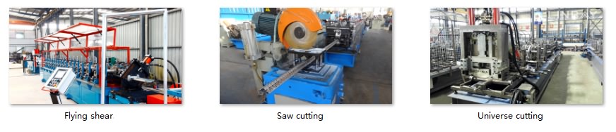
6.Cutting system:Flying hydraulic cutting, the roll former doesn’t stop when cutting.
7.PLC cabinet: Siemens system.
Real case-Machinery
1.Hydraulic decoiler*1
2.Servo feeder*1
3.Hydraulic punch machine*1
4.Roll forming machine*1
5.Hydraulic cutting machine*1
6.Out table*2
7.PLC control cabinet*1
8.Hydraulic station*2
9.Spare parts box(Free)*1
Real case-Description
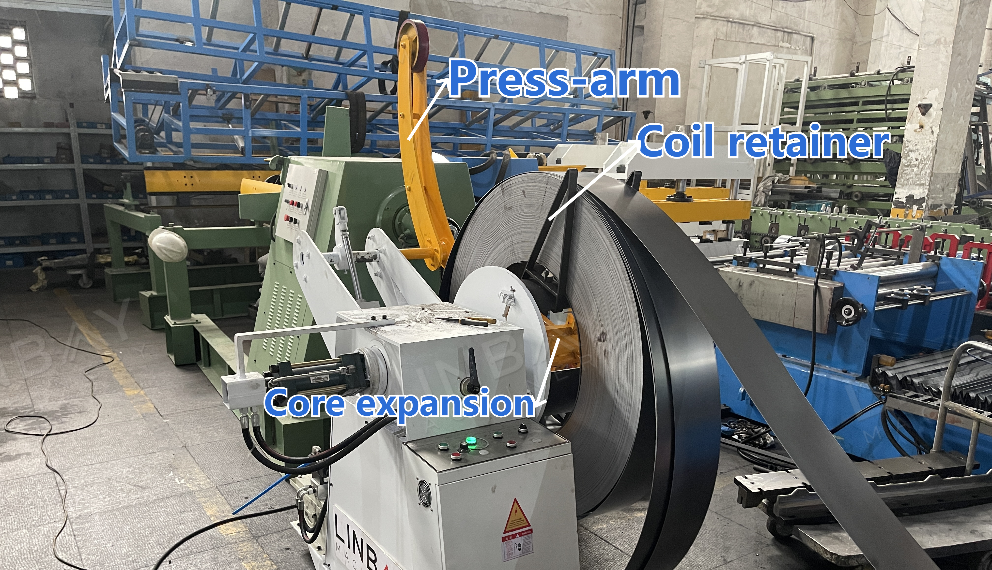
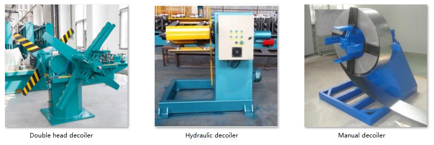
Decoiler
The decoiler's central shaft supports the steel coil and acts as an expansion device, accommodating coils with an inner diameter of 490-510mm. The press-arm device on the decoiler secures the coil during loading, preventing it from springing open due to internal tension and ensuring worker safety.
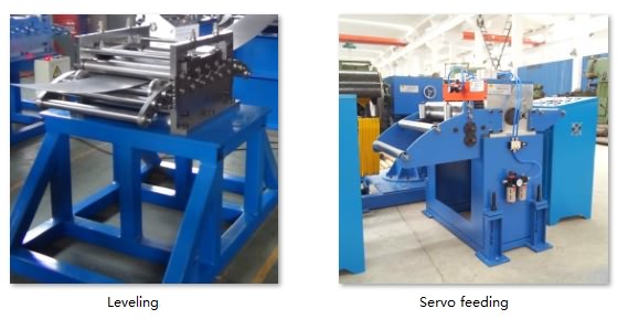
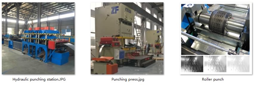
Hydraulic Punch & Servo Feeder
The hydraulic punch, powered by the hydraulic station, creates holes in the steel coil. Cross bracing is punched at both ends, either on the flange or the bottom, based on installation requirements. There are standalone and integrated hydraulic punch machines. The integrated type shares the same base with the roll forming machine and pauses other machines during punching.
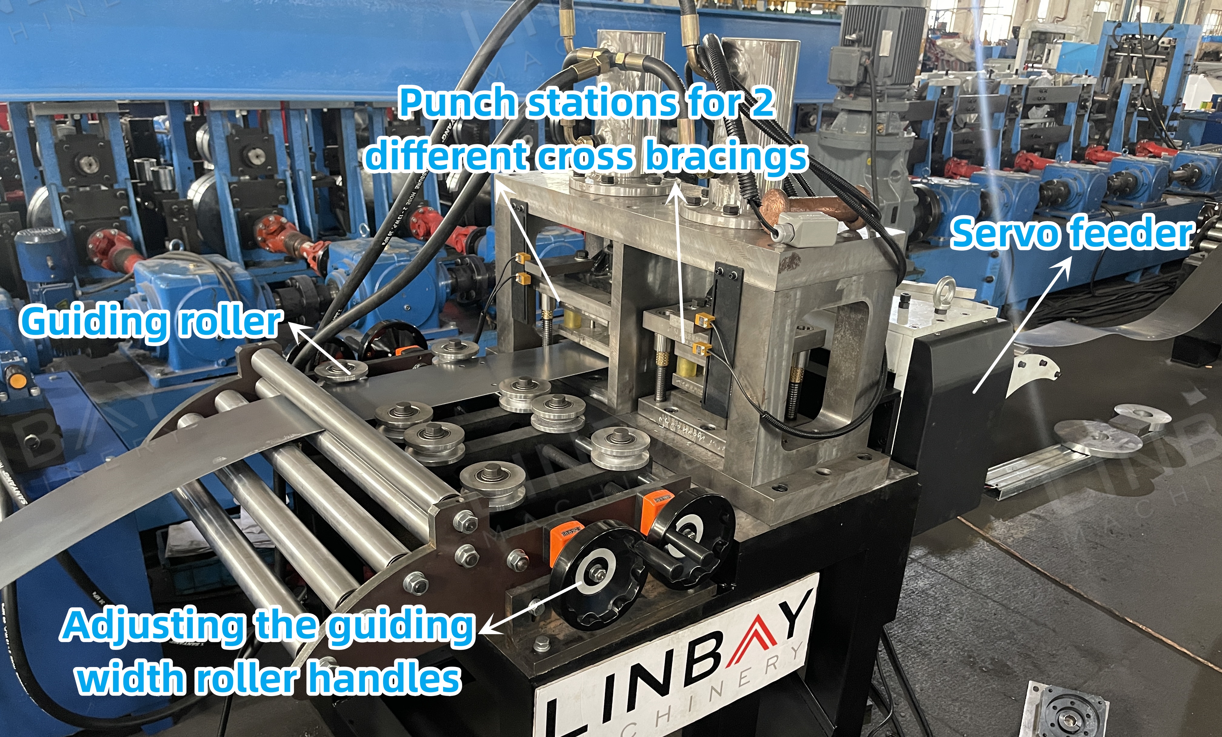
This production line utilizes the standalone version, enabling the decoiler and forming machine to operate continuously during punching, ensuring uninterrupted production. The standalone version includes a servo feeder driven by a servo motor, which minimizes start-stop delays and precisely controls the coil's advance length for accurate punching. The pneumatic feed mechanism inside the feeder safeguards the coil surface from scratches.
Guiding
Guiding rollers ensure proper alignment of the coil and machine to prevent distortion during forming, as the straightness of the cross bracing directly impacts the overall stability of the shelf.
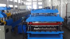
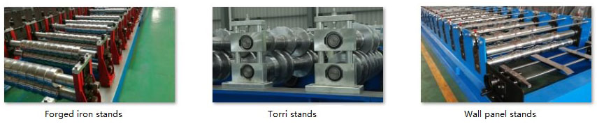
Roll Forming Machine
This forming machine boasts a cast-iron structure and a gearbox system. It's important to note that both rows cannot operate simultaneously. For higher production capacity, we recommend a separate production line for each size.
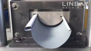
Flying Hydraulic Cutting
The "flying" design enables the cutting machine base to move along a track, allowing continuous coil feeding through the forming machine without halting for cutting, thus enhancing overall line speed.
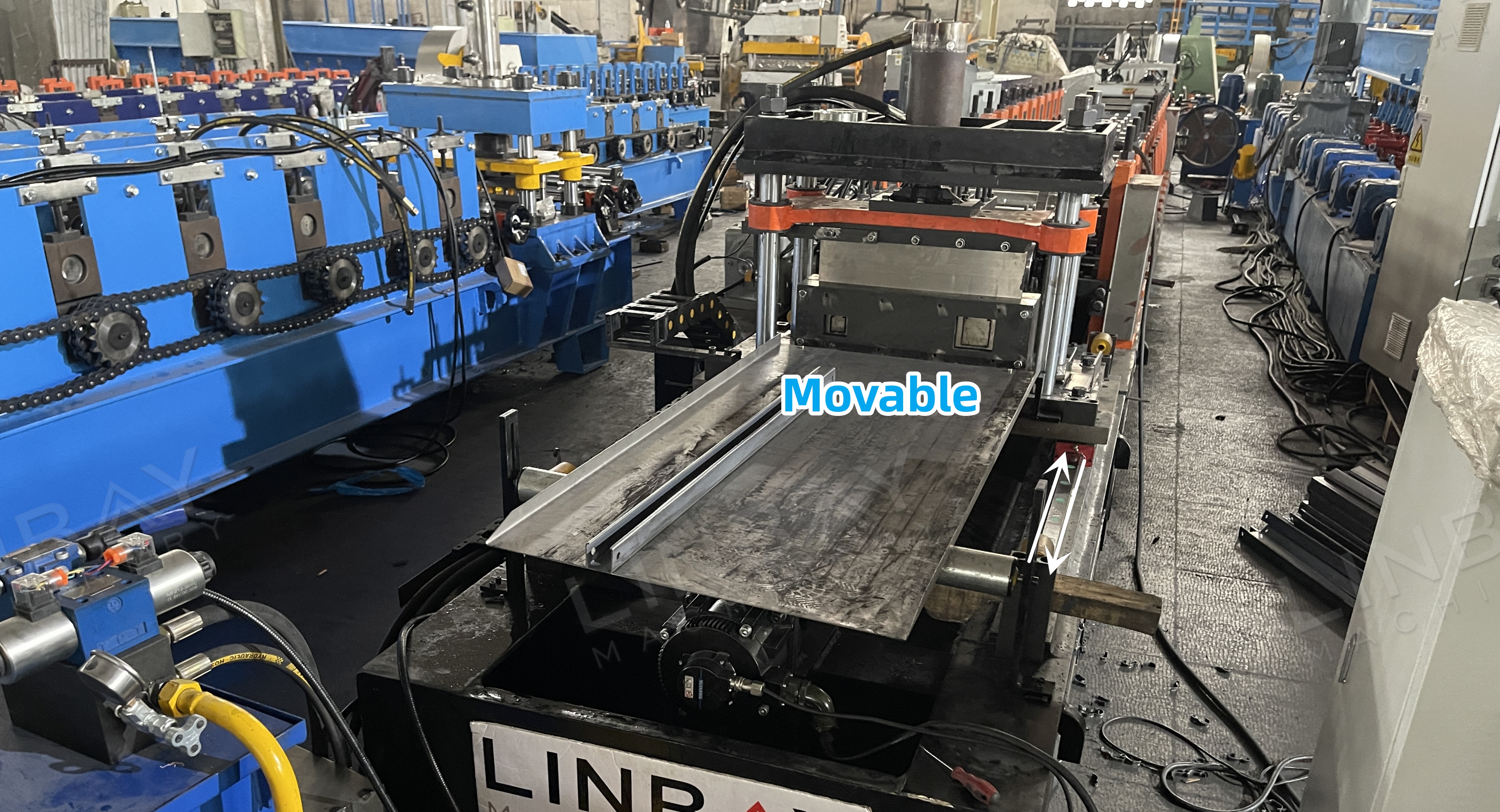
The cutting blade must be tailored to the profile shape, necessitating a distinct blade for each size.
Optional Device: Shear Butt Welder
The shear welder integrates both shearing and welding functions, allowing for the connection of new and old steel coils. This reduces material waste, minimizes coil change time, and simplifies adjustments. It utilizes TIG welding to ensure smooth and flat joints.
Hydraulic Station
The hydraulic station features cooling fans for effective heat dissipation, ensuring continuous operation and enhanced productivity. It is recognized for its reliability and long-lasting performance.
PLC Control Cabinet & Encoder
The encoder transforms the measured coil length into electrical signals for the PLC control cabinet. This cabinet regulates production speed, output per cycle, and cutting length. Thanks to precise feedback from the encoder, the cutting machine achieves a cutting accuracy within ±1mm.
1. Decoiler
2. Feeding
3.Punching
4. Roll forming stands
5. Driving system
6. Cutting system
Others
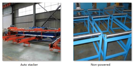
Out table